This is a bit sketchy as to what I was doing as I didn't take a lot of pictures. But it is more about expressing the desire to couple circuits together using an optical coupling. In this case it was the best way to transfer the triggering of an alarm to information that can be stored on the computer. Previous projects built an input to my computer that will log the time it was activated. In this project I have an alarm that sends a beam to a receiver. When the beam is interrupted it it sounds a piezo speaker. I was going to have the current going to the piezo to trigger a relay. The problem came up when I discovered the voltage powering the speaker was AC. However----when applied to an LED it lit it for half the AC cycle----thus appearing to be lit by DC. Since the two circuits (the alarm and my circuit leading into the computer) were not directly compatible---I decided to "opti-couple" them together.
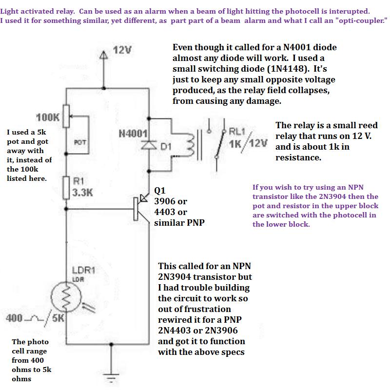
This is the circuit that I use when doing an optical coupling. It is composed of a photo resistor that allows a transistor to go high with voltage, and close a relay, when light is applied to the cell. You can see that I have modified it a bit from what I first had for a schematic. Sometimes you have to play around with it to get the values that work.
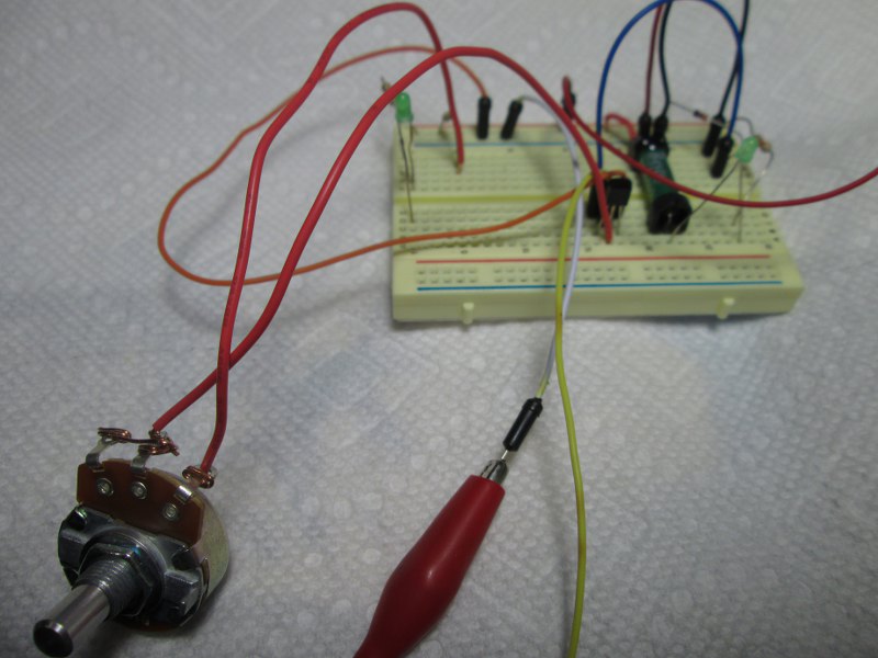
I find it's always best to build it on a breadboard for testing. Then if parts have to be changed to make it work it is easier to do so ----rather than try to after the parts are soldered in place. As usual----grubby focused better on the close potentiometer then on the breadboard he was aiming for.
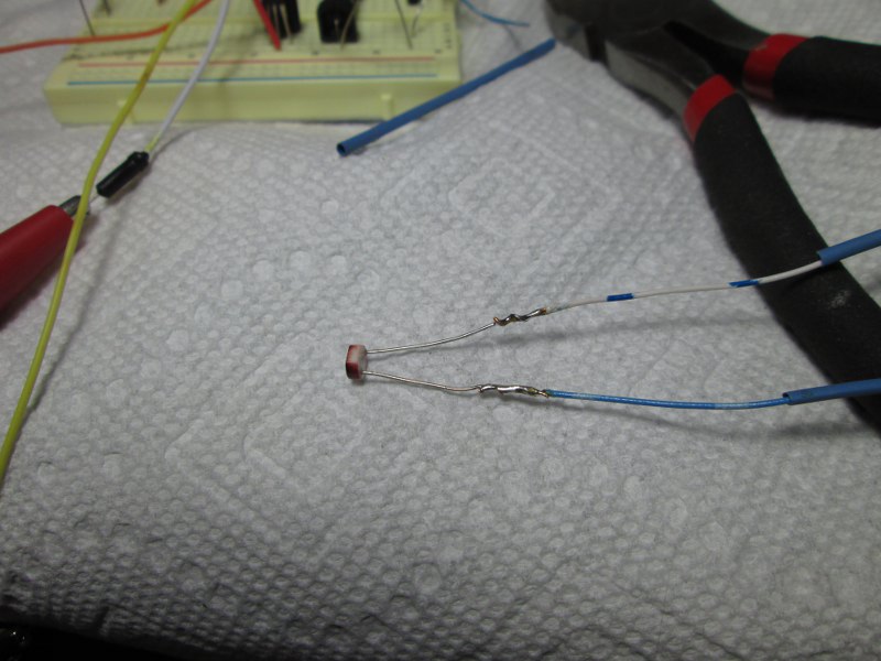
The opti-coupler is made by soldering wires to the photo resistor and covering them with shrink tubing. This will now be ready to receive light. Here are the wires soldered to the photo resistor.
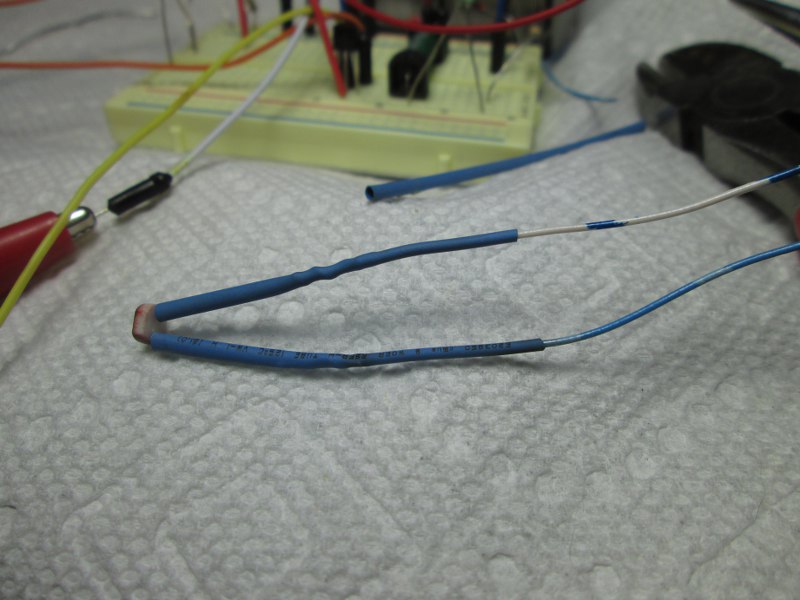
And here is the shrink wrap applied to the wires and legs of the photo resistor. They will later be put into a larger tube of shrink wrap to meet up with an LED.
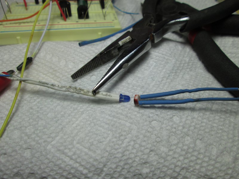
Here is a blue led that is wired in place of the piezo speaker and will generate light when the alarm speaker would have been activated. Grubby found that this blue LED presented the most light for the energy applied to it. Not shown here---but you will see it later----Grubby placed the photo resistor and LED in opposite ends of a larger piece of shrink wrap and pushed them in until they met in the middle. Then the shrink wrap was heated to encase the two in the dark----only to be lit up and activated when the alarm was triggered.
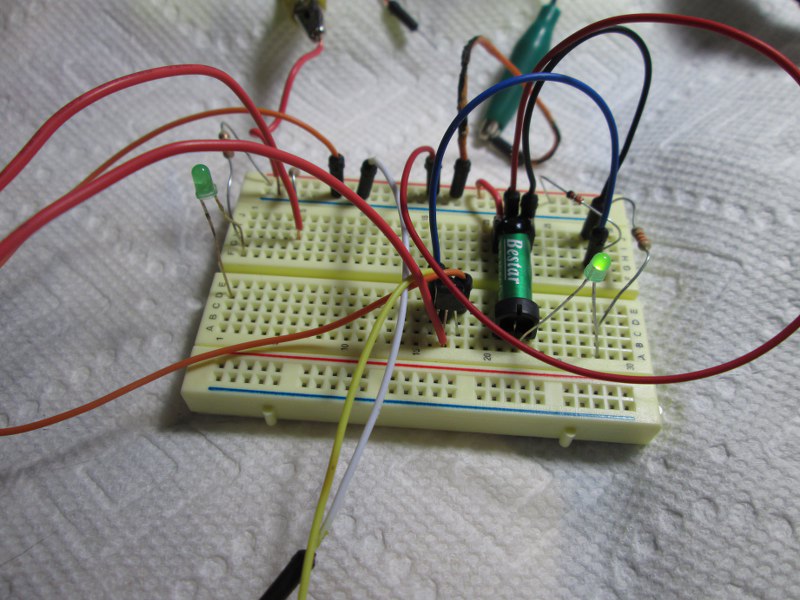
Again the circuit was tested on a breadboard and the green LED is lit showing that the relay has been activated and is closed. The green LED was later removed as it seemed to compromise the circuit that then passed from the relay to the other triggering device that leads into the computer to log the time the alarm is activated.
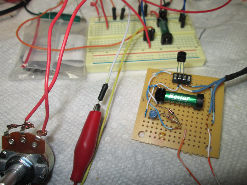
Here the breadboard circuit is transferred to a small printed circuit board. Note the large 100k potentiometer in the left foreground has been replaced with a very tiny 5k blue trim capacitor on the printed circuit board.
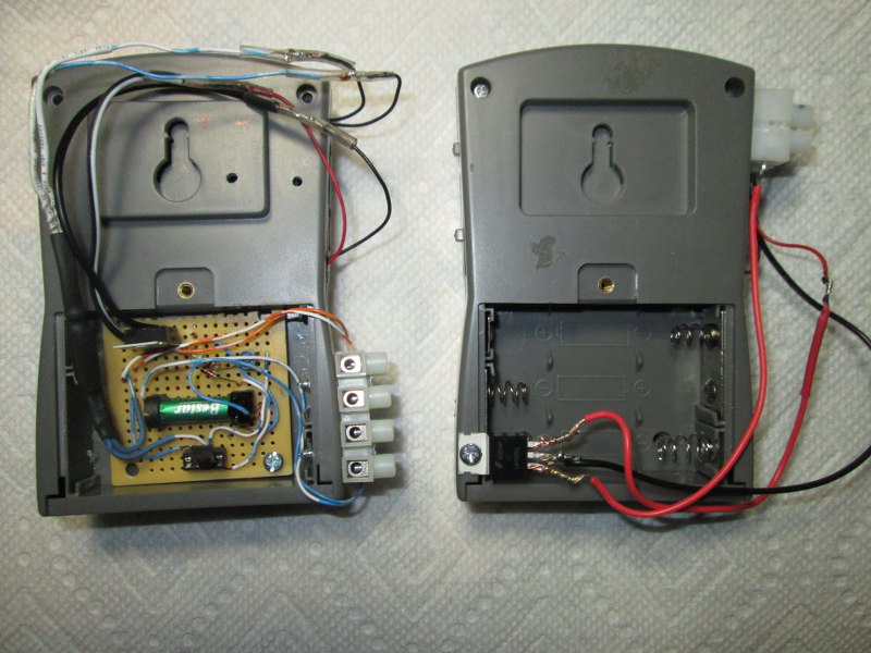
Here is the back of the transmitter and receiver alarm. The transmitter is on the right. Since the opti-coupler circuit needs 12 volts but the alarm circuits were meant to run on 3 batteries----Grubby put in a small voltage regulator in each unit. It's the small three prong unit on the left. It can take up to 35 volts in on the left leg----then the center is the common leg for the transition of 12 volts in and lower voltage out. And the right leg produces the 5 volts out. The left unit is the receiver and has the 12 volt circuit board to run the optical coupler while a small voltage regulator is also incorporated to run the receiver's inner circuit (not showing) on the 5 volts it needs.

Even though you can't see the legs on the voltage regulator, you can see the black shrink wrap that has the LED and photo resistor in it.

Here is another view with the 3 legs showing on the transmitter with the voltage regulator. Nothing fancy about Grubby's solder joints here. He hesitated to overheat the regulator so settled for a partial flow of solder onto the legs. It was more than enough to bound the stranded cable to them though.
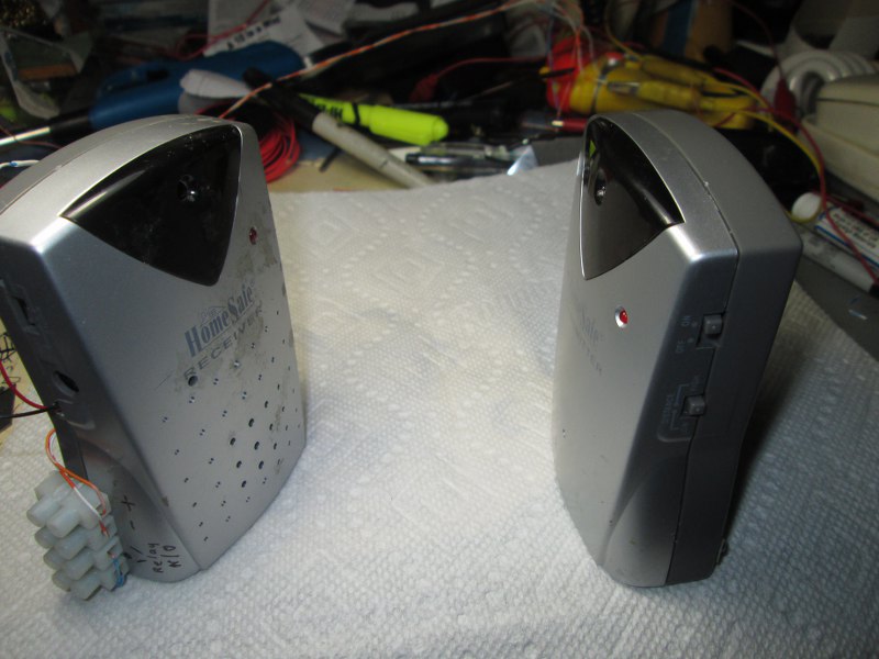
Here is how the units look ready to be put in place to face each other. The receiver on the left has a 4 block terminal for 12 volts in and the relay contacts out. The right transmitter has just a double block (out of sight in the picture) for the 12 volts in----which of course is reduced to 5 volts as explained. So as Grubby said, the details are a bit sketchy. Of course the closing of the relay will be fed into another device (mentioned in Grubby's other projects) that will then trigger a computer to record the time that the beam is broken and the alarm activated. The opti-coupler was the best way to accomplish this. Grubby hopes that it may inspire others to build such a devise----when lost for a way to connect two circuits together---without really connecting them together;-)